
A very good alternative reliable solution for central heating of apartments or houses are solid fuel boilers.

In other words, devices that use fuel from chopped wood or pellet, or even shells or fruit seeds. They usually have a larger combustion chamber than other boilers and collection space (ashtray) for the ash produced. Depending on the fuel they burn, the ash can be removed on a daily basis or more rarely. Their construction materials are steel or cast iron. Their design differs from manufacturer to manufacturer. In these heating installations, the “working medium”, the medium that transfers energy from the source (pellet device or fireplace) to the radiators is water.
We know from physics that all materials expand when heated, and when they cool, they contract. For water, the first part of the sentence applies, that heated expands and increase in volume but not the second part. The water, below 4 ° C, that is, when it cools instead of decreasing in volume… increases, expands. So, when our installation is put in or out of operation, the water is subject to large temperature differences and the purpose of a successful installation is to operate properly and safely even in extreme conditions or when a part in the layout of the installation is damaged.
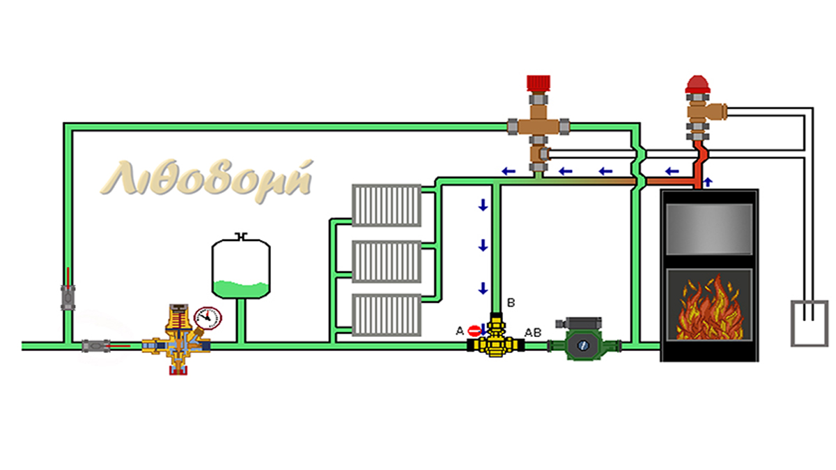
Nowadays, an important, not the only, reason for the prevalence of closed expansion tanks in devices that burn solid fuels, is that we avoid cooling the installation water. In this article we will show you the layout of the heating system with a closed expansion tank. We will refer to the components – parts that make it up and how each participates in the safe operation of the system. In our store we have installed and in full operation, three such systems: wood-burning radiator fireplace, pellet boiler and wood-burning radiator stove. If you want to see them in operation, contact us and we will be happy to light a fire for you.
THE PARTS OF THE CIRCUIT:
Automatic fill unit, closed expansion tank, three-way thermostatic mixing valve, circulator, three-way release thermostat, safety valve.
The automatic fill unit, the closed expansion tank and the installation safety valve are called system pressure retention of the installation and ensure that the installations network pressure will remain within the limits we have set up both towards up and down.
The fill unit undertakes the pressure of the water circuit to be “above” and the safety valve to be “up to” a value.
AUTOMATIC FILL UNIT

The instrument that allows us to fill a heating installation with water is called automatic fill unit. This automatic unit, allows water to pass from the high-pressure side (water supply network) to the low-pressure side (heating network). The pressure in the heating network is usually set at 1.5 BAR. Today’s modern automatic fill unit have a built-in, non-return valve, so in the event of interruption in the water supply network, water doesn’t return from the heating network. Also, includes a manometer pressure indicator. It is connected to the central return pipe and to a place where we can control its manometric reading. Before and after the filler, we install cut-off valves so that it can be removed without emptying the entire water heating network. Except to the initial water filling of the heating network, its purpose is to constantly replenish the installation with water. The water comes out of the installation either from the safety valve, if it opens, or from the vents, or even from small leaks.
CLOSED EXPANSION TANK
 So as mentioned above, when water is heated in a heating system, its volume also increases. So extra “room” should be given to the water to keep the pressure constant. This extra space required is provided by the closed expansion tank. The expansion tank is a closed metal container that is divided into two spaces: a closed one filled with air (nitrogen) and one open with water. They are separated from each other by a moving elastic membrane.
At rest (a) the container is filled with air which pushes the membrane to the walls of the container. When we fill the network (b) with water, due to the water pressure a part of the container is filled with water until the air and water pressure balances. When the installation is in operation (c) the network water, expands as it gets heated, increases its volume and presses the membrane, even more towards the air.
The closed expansion tank receives the water contraction by keeping the system pressure constant.
SAFETY VALVES
In a central heating installation, safety valves do not allow the water pressure to rise, above a predetermined value. They are connected to the adduction very close to and above the boiler. Between the safety valves and the boiler there should be no obstruction (valves, reversing, etc.). They open and remove hot water from the installation if the pressure exceeds a predetermined value. The most likely causes of high-water pressure are:
- damage to the hydrostat or to the circulator resulting in the large swelling of the water volume to the point that the expansion tank cannot absorb this increase in volume.
- Incorrect initial setting of the tank’s expansion pressure.
- poor regulation of the automatic fill unit or its failure.
- damaged membrane of the closed expansion tank.
Their operation is based on the force exerted by a spring on a piston, which seals a water outlet to the environment. If the water pressure increases, creating a force greater than that of the spring, the piston will recede and the water will run from the installation to the environment until the pressure is reduced so that the force of the spring can hold it.
 It should be noted here that safety valves are not and should not be part of the operation of the heating system but part of its safety. They only work when something goes
  wrong.The thermal safety valve is a double valve for increasing pressure and increasing temperature. The thermal safety valve opens at a temperature of 92 ο C and pressure of 4 bar. Once the valve is opened, the water is drained into the sewer in order for temperature and pressure to remain within normal limits. Especially when it comes to a wood boiler, a thermostatic overheating valve must be installed. This valve is activated when the water in the boiler tends to exceed 95 ο C.
When activated, it opens and sends a quantity of water to the sewer, while at the same time, inserts the same amount of cold water from the water supply network, thus reducing the waters temperature in the boiler.
CIRCULATOR
 Circulators are the special category of pumps that aim to put the network’s water into circulation. The forced circulation of water is carried out by these centrifugal pumps driven by electric motors. The right choice of circulator requires knowledge of two parameters, which result from the hydraulic study of the heating network: the water supply, meaning how many cubic meters / hour should be circulated in the installation and the manometric height, i.e. the friction in the pipes that must be overcome by the circulator so that the water reaches the most difficult parts of the installation. Nowadays, smart circulators have been developed that control differential pressure or operating pressure depending on water demand. They have an electronic card with a microprocessor thus ensuring continuous control of the electric motor. When we connect the circulator to the circuit, we must install valves in front of and behind it, so that we can remove it in case of malfunction.
THREE-WAY THERMOSTATIC MIXING VALVE
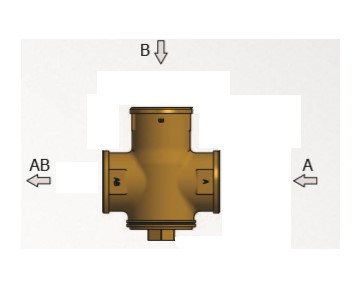
The valves of this category have as their mission the protection of the boiler from low return temperatures and the smooth operation of the installation. Maintaining a high and constant temperature in the water of the return network results in high operating efficiency, reduced tar emissions and prolong boiler life. The valve is installed on the return. At the startup of the boiler, the water follows the path from B to the AB outlet, up to a predetermined temperature (thermostat adjustment is usually at 55° C). For the temperature range from 55 ° C to 65 ° C, the water passes through both A and B outlets and exits from AB. When the thermostat detects a temperature at inlet A of 65 ° C then inlet B closes completely and water only passes through inlet A.

The simple operation mode of the DIGITAL TECHNICAL PANEL is by activating the circulator at a given, predetermined temperature. In the installation we present to you, the temperature is 45 ° C.